Chapter 4. Device and component modelling with algebraic equations
4.1 The role of algebraic and numeric equations in circuit simulation
Algebraic/numerical equations play the following important roles in circuit simulation:
- Circuit device parametrization,
- Post-processing of simulation data, and
- Definition of user-defined components.
With the spice4qucs subsystem the first and second operations in the above list and the third item can be performed easily.
Spice4qucs supports the following algebraic/numeric equations:
1. The usual Qucs equations. These are converted automatically to SPICE .PARAM statements
and ngnutmeg scripts. Equations that don’t include simulation variables (for example, node voltages
and device currents) are passed as .PARAM statements in the generated
SPICE netlist.
In contrast equations that include one or more simulation variables are placed
in the SPICE simulation file between the ngspice .control and .endc statements.
The .control and .endc block is normally located following one or more SPICE simulation commands.
Please NOTE equations which include simulation variables can only be processed with ngspice because Xyce
is not equipped with a suitable post-processor for this purpose.
.PARAMitems. Such statements are passed directly as a.PARAMentry in a generated SPICE netlist.
3. .GLOBAL_PARAM sections. This feature works in the same manner as a
.PARAM item.
4. .OPTIONS sections. This feature provides a way of changing the value of internal ngspice or Xyce
defined variables, such as, for example GMIN.
5. Ngnutmeg scripts. These are directly passed to the ngnutmeg post-processor after simulation.
Again please note this feature is not supported by Xyce.
Icons representing the last four equation types can be found in the Spice sections group of the Components palette.
4.2 Qucs equations usage with ngspice and Xyce
Ngspice fully supports equations. Only mathematical functions
related to S-parameter simulation will (such as stoz(), stoy(), etc.) are niot implemented.
Complex number arithmetic is also supported. Similarly, physical constants (q,
kB, etc.) are also allowed. Qucs equations can be used for both
parametrization and post-processing purposes. However, please remenber that SPICE variable names are not case
sensitive but Qucsator is case dependent. Hence, Kv and KV refer to different variables for Qucsator
and the same variable for ngspice and Xyce. Algebraic expressions are evaluated from the left to right with
brackets, in the normal fashion, determining evaluation order.
As mentioned above, equations that contain simulator variables, such as node
voltages and device currents, are converted into ngnutmeg script. The following
example (complex power calculation in RC-circuits, Fig 4.1) illustrates the
usage of Qucs equations with ngspice. This circuit simulates correctly with both
ngspice and Qucsator.
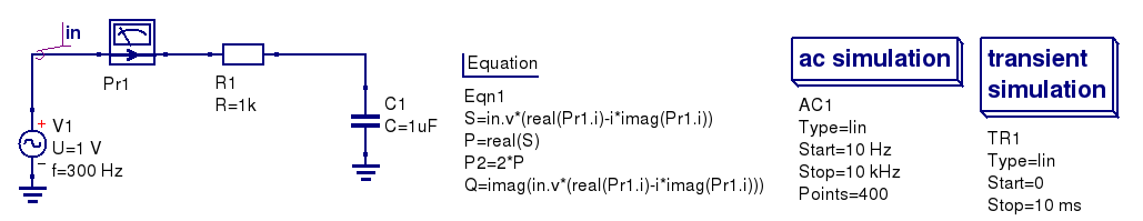 Figure 4.1 Total power in an RC-circuit.
It’s need to evaluate the following equations:
Total power
Active power:
Reactive power
The simulated results are shown in the Figure 4.2.
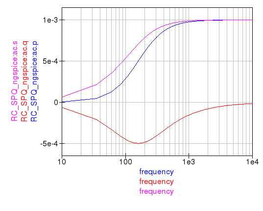
Figure 4.2 Total, active, and reactive power curves.
The Xyce circuit simulator is distributed without a post-simulation data processor like ngnutmeg. Unfortunately, this implies that Xyce can only partial process Qucs equations. In particularly, Xyce only supports parametrization. Algebraic equations that include node voltages or device currents are ignored by Xyce.
Here is a small example. It illustrates how parametrization could be used with all of three simulation back ends. Parametrisation is used to estimate the resonant frequency \(f_{res}\) of the RCL circuit:
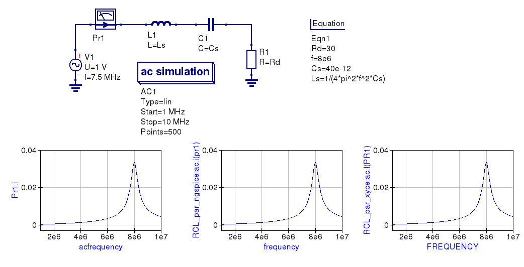
Figure 4.3 Parametrised RCL-circuit.
You can see that simulation results for all three circuits are identical.
NOTE:
There is an important note on equations order. SPICE simulators are succeptible
to equations order, but equations order has not matter for Qucsator. It
concerns both parametric equations and postprocessor equations. Spice4qucs
don’t care on equations order. User should select proper equations order to
avoid Undefined variable... simulation errors. This concern also two or
more Equation components on schematic.
4.3 Manipulating simulation data with algebraic measurement scripts
Post-processing of the simulation data is very important feature of a circuit simulator. There are two general ways employ data postprocessing with ngspice and qucsator.
Firstly, a special component Nutmeg Equation has been implemented. It works in a similar fashion to the established Qucs Equation component. It’s properties dialog (Fig.4.4) is opened by double clicking on the Nutmeg Equation icon.
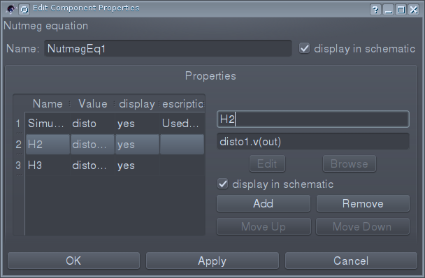
Figure 4.4 The Ngnutmeg Equation properties dialog.
You need to specify (as first parameter) the type of simulation to which the ngnutmeg script is be linked. The following simulation types are allowed:
- AC
- TRAN
- DISTORTION
- DC
- All simulations
If type “All simulations” is selected, equations will be evaluated for all
simulations. You should use the standard SPICE notation for node voltages and device current, for example;
node voltages are specified as v(node) or V(n1, n2). In a similar
fashion probe currents are specified in SPICE terms as VPr1#branch which
represents the current flowing in Qucs probe named Pr1.
Spic4qucs allows the use of all of the ngnutmeg functions and operators without any limitations.
However, please take into account that variables in ngnutmeg equations are case independent!
All other equations/parameters form ngnutmeg equations. These are converted into ngnutmeg let statements:
let Var1 = Expression1
let Var2 = Expression2
let VarN = ExpressionN
Expressions are evaluated from the first to last with brackets determining the order of priority. You should take into account expression order when writing ngspice equations.
The following example (Fig.4.5) illustrates how the two equation types are used.
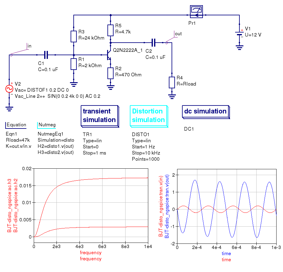
Figure 4.5 Distortion analysis with ngnutmeg simulation data postprocessing.
The second way of postprocessing simulation output data uses the normal Qucs Equation component. However, please note thar spice4qucs allows the use of SPICE notation in Qucs equations. The following example shows how this feature can be utilized.
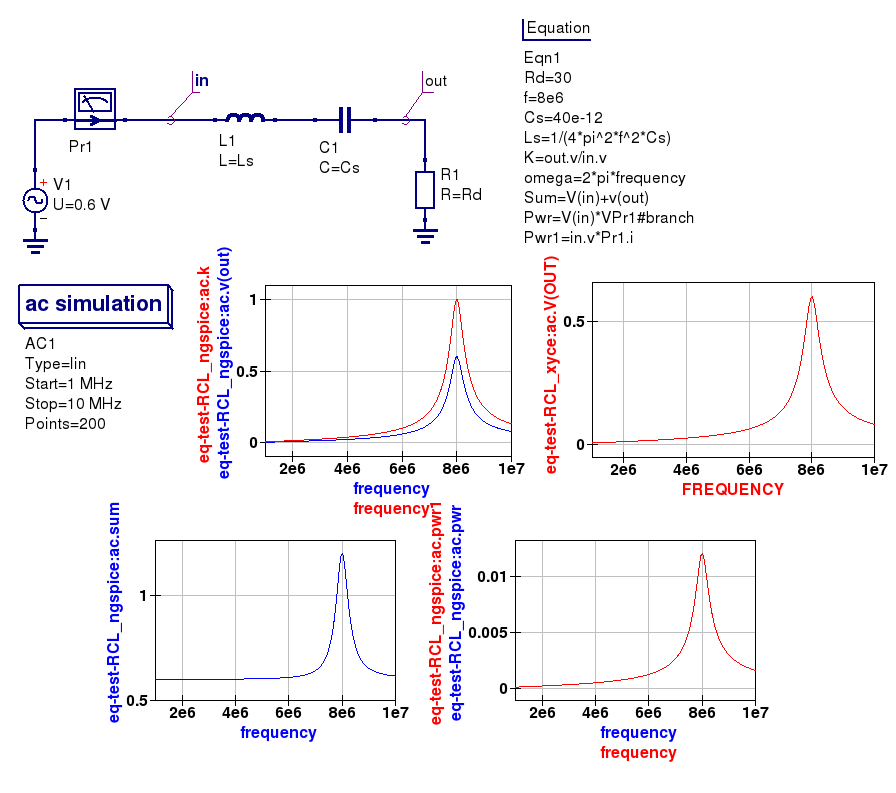
Figure 4.6 Using SPICE notation in Qucs equations.
4.4 Qucs Equation-Defined Device (EDD) models
Qucs EDD models are described by current equations and charge equations. EDD has \(N\) branches. Current equations bind current \(I_N\) flowing through a branch with voltage \(V_N\) across branch \(N\):
Charge equations bind charge \(Q_N\) accumulated by a branch with voltage \(V_N\) across branch \(N\) and current \(I_N\) flowing through branch \(N\):
Qucs equation notation must be used in EDD equations. Qucs notation is converted to SPICE notation automatically, where the Qucs EDD function is synthesised by a SPICE netlist builder to form an electrical equivalent circuit built around SPICE B-type sources.
The Spice4qucs subsystem supports both EDD current and charge equations. You can simulate EDD models with ngspice and Xyce without any special adaptations. All SPICE mathematical functions are allowed. The following examples (Figures 4.7 and 4.8) demonstrate how EDD based circuits are simulated.
The first example illustrates a set of IV-curves for a Tunnel diode, where the Tunnel diode IV-curve is approximated by the following equation:
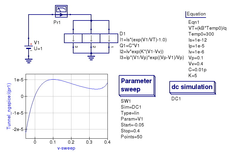
Figure 4.7 Tunnel diode simulation using an EDD compact device model.
The second example illustrates how a nonlinear capacitor can be approximated by a polynomial that binds capacitor charge \(Q\) with applied voltage \(V\)
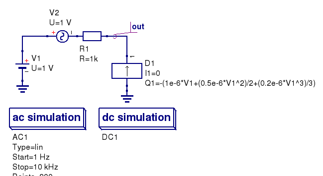
Figure 4.8 A non-linear capacitor simulation using ngspice and Xyce
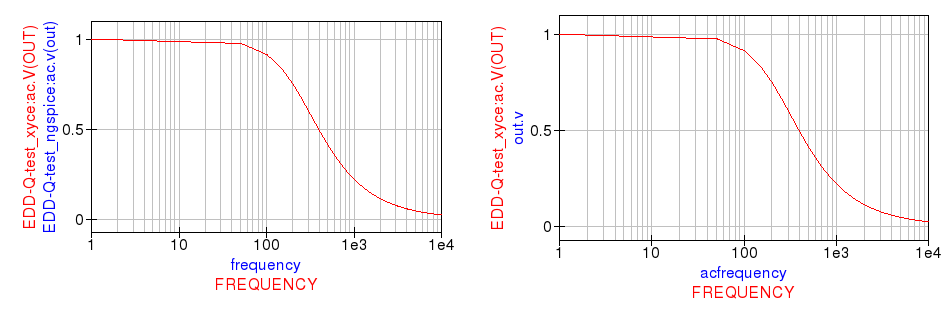
Figure 4.9 The magnitude response of an RC circuit with a non-linear capacitor.
The spice4qucs special component called Equation defined source could be used as alternative to the Qucs EDD. This component is located in group Spice components. It implements a behavioural B-type SPICE voltage or current source. See chapter 5.1 of ngspice manual for more information. The example introduced in Figure 4.10 shows how this source is used. Please note that SPICE notation must be used with B-source expressions.
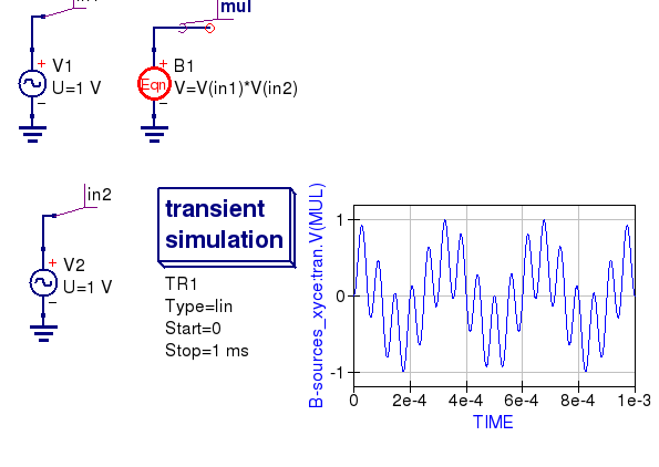
Figure 4.10 A voltage multiplier model with B-type sources.
4.5 Qucs Frequency Equation-Defined Device (FEDD) models
Qucs RFEDD devices is not yet supported by spice4qucs. As a temporary work around behavioural R,C,L
models and B-type sources should be used instead. Moreover, the ngspice
hertz variable is defined
to represent signal frequency, allowing models with the same function as the Qucs RFEDD model to be synthesised.
Refer to chapters 3.2.4, 3.2.8, 3.2.12, and 5.1 of the official ngspice manual for further information.